OBD2 connector and pinout
Quick answer
The OBD2 connector is a standardized 16 pin trapezoidal shape, defined under SAE J1962, with pin 4 and pin 5 always carrying chassis and signal ground, pin 16 always carrying constant battery power, and the remaining pins carrying whichever of the five OBD2 signaling protocols that specific vehicle uses, which is why the connector shape is universal even though not every pin is active on every car.
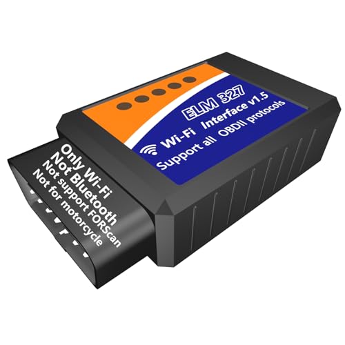
WiFi ELM327 OBD2 Adapter WiFi ELM 327 OBD Scanner for Universal 12V Vehicle
A simple wifi dongle is a low cost, low risk way to physically explore the connector and confirm which pins your specific vehicle is actually using, without paying for functions beyond basic code reading.
Coverage varies by tool and by model year, so check a specific tool against a specific vehicle before buying.
Where the connector is usually located
SAE J1962 requires the connector to be accessible from the driver's seating position without tools, generally within about two feet of the steering wheel. In practice this most often puts it under the dashboard near the steering column, though the exact location, orientation and any cover panel varies significantly by manufacturer and model. Always check your specific vehicle's owner's manual or a source covering your exact make and model to confirm the precise location, since it is not identical across all vehicles.
Why the connector shape is standardized but the pins are not all used
The physical 16 pin trapezoidal shape and pin spacing is fully standardized, which is why any OBD2 scan tool physically plugs into any OBD2 compliant vehicle regardless of make. What is not standardized is which pins carry an active signal, since that depends on which of the five OBD2 protocols the vehicle's manufacturer implemented. A CAN based vehicle uses pins 6 and 14. A vehicle using an older ISO protocol uses pin 7 instead, and possibly pin 15. This is why a scan tool needs to support the correct protocol, not just fit the connector, to actually communicate.
The pins that are always the same across every vehicle
Regardless of which signaling protocol a vehicle uses, three pins are standardized across the entire OBD2 mandate: pin 4 for chassis ground, pin 5 for signal ground, and pin 16 for constant battery positive voltage. These three pins are why a scan tool can always draw power directly from the connector without a separate battery or cable, and why grounding is consistent across every vehicle regardless of protocol.
What happens if a pin is damaged or bent
A bent, corroded or missing pin on the vehicle's connector, or a scan tool cable with a damaged pin, is a common and often overlooked cause of a scan tool failing to connect at all, sometimes mistaken for a deeper electrical fault. Since pins 4, 5 and 16 in particular are required for basic power and ground, damage to any of those three specifically will typically prevent the tool from powering up or communicating at all, while damage to a protocol specific pin may only prevent communication on vehicles using that specific protocol.
How to visually check your connector before assuming a deeper problem
Before assuming a scan tool failure means an electrical fault in the vehicle, physically inspect the connector for bent pins, corrosion, or debris lodged inside the housing. A flashlight and a close look are often enough to catch a bent pin that is preventing a solid connection. Gently straightening a bent pin with a small precision tool can resolve a connection issue that otherwise looks like a much larger problem.
Why an aftermarket cable or dongle sometimes will not connect when a factory tool does
An inexpensive dongle or cable that only supports a subset of the five OBD2 protocols will fail to communicate with a vehicle using a protocol it does not support, even though the connector fits perfectly and every pin is intact. This looks identical to a wiring fault from the user's side but has nothing to do with the vehicle at all. Checking that a scanner explicitly lists support for your vehicle's protocol, generally CAN for anything from 2008 forward, avoids this specific and common source of confusion.
| Pin | Assignment | Used by |
|---|---|---|
| Pin 2 | SAE J1850 bus positive | GM and Ford vehicles using J1850 protocols |
| Pin 4 | Chassis ground | Every OBD2 compliant vehicle |
| Pin 5 | Signal ground | Every OBD2 compliant vehicle |
| Pin 6 | CAN high (ISO 15765-4) | Every vehicle using the CAN protocol, mandatory since 2008 |
| Pin 7 | ISO 9141-2 / ISO 14230 K-line | Chrysler and many European and Asian imports before CAN adoption |
| Pin 10 | SAE J1850 bus negative | Ford vehicles using J1850 PWM |
| Pin 14 | CAN low (ISO 15765-4) | Every vehicle using the CAN protocol, mandatory since 2008 |
| Pin 16 | Battery positive voltage (constant) | Every OBD2 compliant vehicle |
Equipment mentioned here
- LJPXHHU
OBD2 Bluetooth Scanner Car Code Reader for iOS, Android and Windows
- wireless
$13.98 Check pricePrices change often - Veepeak
Veepeak Mini Bluetooth OBD2 Scanner Code Reader for Android (NOT for iOS)
- wireless
$14.99 Check pricePrices change often - UMEIJA
OBD2 Scanner Diagnostic Tool, Car Scanner for iOS & Android, Bluetooth 5.4
- wireless
$29.99 Check pricePrices change often - Vgate
Vgate iCar Pro 2S Bluetooth 5.2 OBD2 Car Scan Tool for iPhone, Android, and Windows
- wireless
$37.99 Check pricePrices change often




Common questions
Is the OBD2 connector always in the same spot on every car?
The standard requires the connector to be reachable from the driver's seat without tools, generally within about two feet of the steering wheel, but the exact placement, orientation and any cover vary by manufacturer and model. Check a source specific to your vehicle if you cannot locate it under the dash near the steering column.
Why does my scan tool power on with no vehicle connected?
Some scan tools include an internal battery or can be powered over USB independent of the vehicle. A tool that relies entirely on the vehicle's connector for power, drawing from pin 16 and grounding through pins 4 and 5, will not power on unless properly connected to a vehicle with those pins intact.
Can a bent pin in the connector really stop a scan tool from working?
Yes. A bent, corroded or recessed pin, particularly on the ground or power pins, can prevent a reliable connection even though the connector looks intact from a quick glance. This is a common and often overlooked cause of scan tool connection failures.
Do all 16 pins carry an active signal on every vehicle?
No. Only a subset of the 16 pins is active on any given vehicle, depending on which OBD2 signaling protocol that manufacturer used. The physical connector shape is universal, but the actual wired pins vary by protocol and manufacturer.
What is the difference between pin 6/14 and pin 7 on the connector?
Pins 6 and 14 carry the CAN high and low signal lines, used by every vehicle required to implement CAN, which became mandatory across the industry by 2008. Pin 7 carries the K-line used by older ISO 9141-2 and ISO 14230 protocols, common on vehicles from the late 1990s and early 2000s before CAN became universal.